Focus and Alignment of Mercury and Xenon Arc Lamps
Mercury and xenon arc lamps are now widely utilized as illumination sources for a large number of investigations in widefield fluorescence microscopy. Visitors can gain practice aligning and focusing the arc lamp in a Mercury or Xenon Burner with this interactive tutorial, which simulates how the lamp is adjusted in a fluorescence microscope.
Each time the tutorial initializes, the arc lamp adjustment sliders are reset to a random position with the arc image projected onto the stage plate in some condition that deviates from optimum adjustment. To operate the tutorial, first select a lamp type (either Mercury or Xenon) with the radio buttons in the lower portion of the tutorial window. Next, adjust the Collector Lens Focus slider until one or two bow-tie shaped images (simulating a focused image of the arc and its mirror image) appear in the window. Use the Lamp House Mirror Position slider to make the intensity of the two arc images approximately equal. The Arc Lamp Horizontal and Vertical sliders are utilized to overlay the two arc images, so they should be adjusted to merge the images into a single image. When the sliders have been adjusted to produce a small arc image in the center of the window, use the Collector Lens Focus slider to enlarge the arc image until it fills the entire window with a uniform field of illumination in a symmetrical manner to ensure the lamp arc is correctly aligned. In order to reset the tutorial to another random set of adjustment positions, use the mouse cursor to click on the blue Reset button.
The recommended sequence for focusing and aligning an arc lamp is presented in Figure 1. Initially, a lamp that is freshly installed and unaligned may have a variety of orientations when the arc is focused by adjusting the collector lens. An example is illustrated in Figure 1(a), where the arc image is positioned in the upper left and the mirror image is displaced to the lower right. After aligning the arc images and adjusting the mirror position and focus, an image similar to that shown in Figure 1(b) should appear. Merging the arc image into its mirror image will result in an overlap such as the one illustrated in Figure 1(c). Finally, when the collector lens is defocused to illuminate the entire viewfield (Figure 1(d)), an evenly distributed and symmetrical beam should result. If this is not the case, the arc should be re-focused and the alignment procedure started fresh. Visitors are encouraged to practice using the tutorial until they can easily achieve these results.
Figure 1 - Arc Discharge Lamp Focus and Alignment Sequence
The mercury short-arc lamps commonly utilized in fluorescence microscopy are gas-discharge lamps that contain a mixture of liquid mercury and an inert gas (such as argon or xenon), housed within a glass envelope together with a pair of closely spaced electrodes. In contrast, xenon arc lamps contain pure xenon gas. When current is applied to the electrodes, a discharge electrical arc occurs in the gap between them, which produces enough heat to vaporize the mercury and create a high-pressure internal atmosphere. Because the arc is limited to only a few millimeters in size, arc discharge lamps approximate an ideal point source of illumination that is useful for microscopy. These lamps emit a very intense light having a color temperature around 5500K. In a mercury arc lamp, plasma balls are located adjacent to both the cathode and anode, and each has approximately the same intensity, which is twice that in the center of the arc. In contrast, the single plasma ball in a xenon arc lamp is located closer to the anode and is nearly five times as bright as the light intensity surrounding the cathode.
After installing a new bulb in a mercury or xenon arc lamphouse, the arc must be carefully aligned and focused to achieve a homogeneous field of illumination for observing and imaging specimens. The arc itself is very small (about 1 or 2 millimeters in length), and the image of the arc must be positioned along the optical axis of the microscope, at the center of the condenser aperture in the vertical illuminator, to ensure even illumination. The average lifetime of a mercury arc discharge lamp varies between 200 and 300 hours, depending upon the burn switch cycle and the design specifications. Xenon arc lamps typically have a lifetime between 400 and 600 hours. Always follow the manufacturer's instructions for operation and maintenance of arc lamps to ensure maximum lamp lifetime and operator safety.
Aligning and Focusing Arc Lamps
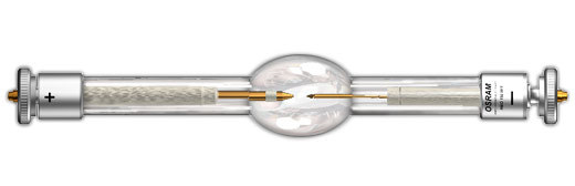
Turn off the power supply and allow the old lamp to cool before installing a new lamp according to the manufacturer's instructions. Pay careful attention to the bulb orientation during installation. Most bulbs (an example is illustrated in Figure 2) are designed to be operated in a vertical position with the anode (+ electrode) underneath, and have a larger end cap on the anode side of the bulb. Bulb mounting sockets in the microscope lamphouse have different diameters to aid in bulb orientation. Because arc lamp glass envelopes are filled with mercury or xenon gas at moderately high pressure, never handle these lamps when they are hot to avoid applying a mechanical force that might cause the lamp to explode. Avoid touching the new lamp with ungloved fingers, because oils from the hands are acidic and may etch the quartz envelope enough to weaken it. In addition, residue from fingerprints can become fused to the exterior of the bulb when it becomes hot. If a bulb does explode, refer to local safety procedures and practices for handling a mercury cleanup and decontamination.
Figure 2 - Mercury Arc Lamp
After installing the new lamp, turn on the power supply and allow the lamp to stabilize for 10 to 15 minutes (Important Note: always allow a new lamp to burn in for at least an hour when it is first turned on). A burn in period is necessary in order for a small pit to be etched into the anode and create a path of least resistance, which enables the arc to remain steady and not wander (flicker) during the useful lifetime of the bulb.
Place neutral density filters in the light path that are sufficiently dense to block approximately 90 to 95 percent of the incident light. A majority of the fluorescence vertical illuminators on modern microscopes are equipped with neutral density filters built into slider frames that can be pushed into the light path to reduce illumination intensity. If the microscope is not equipped with a filter holder of this type, investigate a suitable location for placement of an aftermarket neutral density filter.
Select a suitable fluorescence filter cube for viewing the lamp arc and place it into the light path. Most manufacturers recommend a cube having an excitation filter that passes light in the green region of the spectrum for this purpose.
Place a white piece of paper or note card on the microscope stage directly under the nosepiece. Remove an objective from the nosepiece and rotate the empty hole into the light path, directly over the white paper. Next, open the shutter slider or knob on the vertical illuminator to enable light to pass through to the nosepiece. At this point an illuminated circle of light should be visible on the white paper with a hot spot that may be off center. If the light is too bright, add more neutral density filters. It is also a good idea to wear glasses (either polymer or glass) or to install a tinted breath shield on the microscope to block reflected ultraviolet light from entering the eyes.
Figure 3 - Nikon HMX-4 Mercury/Xenon Lamphouse
To begin alignment of the arc lamp, focus the collector lens (see Figure 3) to produce a sharply defined image of the arc on the white paper. Centering knobs built onto the lamphouse exterior can then be used to translate the focused arc image directly into the center of the illumination circle produced on the white paper. Some lamphouses have an internal mirror system that directs a more intense illumination into the aperture. Microscopes equipped with this type of lamphouse will produce two arc images (the actual arc and its mirror image). Use the mirror centering and lamp translation knobs (Figure 3) to position the real arc and its mirror image (which is usually less intense) side-by-side, and then use the mirror focus knob to adjust the intensities until they are approximately equal (lamphouses lacking the mirror system will also lack the adjustment knobs, so carefully check the manufacturer's instructions on lamp adjustment). Finally, use the lamp adjustment knobs to overlay the arc and mirror images as closely as possible.
After the focused arc image (and its mirror image, in lamphouses so equipped) is perfectly aligned in the center of the optical path (and the illumination spot on the white paper), slowly defocus the lamp collector lens with the appropriate adjustment knob. As the lens is defocused, observe the beam as it expands to ensure that it fills the area in a uniform manner and is not displaced to one side. If the arc image does not expand symmetrically, refocus the arc and repeat the alignment procedure. Finally, bring the arc image back into focus and reinsert the objective. To ensure completely uniform illumination, it may be necessary to make additional minor adjustments to the collector lens while viewing a uniform specimen through the eyepieces with the objective in place.
A majority of the microscope manufacturers offer an optional alignment accessory to facilitate the centering of the image of the lamp arc to the rear aperture of the objective. At its upper end, this accessory either has the standard Royal Microscopical Society (RMS) thread or 25-millimeter threads to accommodate newer nosepieces, and can be screwed into the nosepiece in place of an objective. In order to use the accessory, it is first placed in the nosepiece and then rotated into the light path. The lower face of the accessory has a frosted, orange-colored glass window with an inscribed crosshair (as illustrated in Figure 4). Light passing through the microscope dichromatic mirror strikes the built-in reflector of the centering screen and is reflected onto the crosshairs. As the lamp condenser knob and the centering screws on the lamp socket are manipulated, the image can be observed and translated so that it is centered to the crosshairs. The size of the image of the arc can be made bigger or smaller by manipulating the collector lens focus position. After the arc is aligned, the centering accessory can be replaced by a regular objective.
Figure 4 - Arc Lamp Alignment Accessory
Regardless of whether alignment of the arc is accomplished with the aid of an accessory or with a white piece of paper placed on the microscope stage, both methods project the arc image that is present at the entrance pupil of the objective, in effect, the rear objective aperture. When the objective is in place, the image of the arc at the rear aperture is out of focus and the illumination at the image plane (that of the field diaphragm) is uniform. This is the essence of Köhler illumination.
As digital imaging workstations become more popular and microscopes equipped with high-end camera systems grow more complex, it is important to remember how dangerous the arc lamp power supply can be to electronic equipment. Always turn the arc lamp on before powering on auxiliary computer or camera equipment that is in close proximity to the power supply, and always turn this equipment off before turning off the arc lamp. The cable supplying current to the lamp from the power supply is generally quite well shielded, but a momentary 20,000 to 50,000 volt surge is possible when the lamp is fired. This large voltage can generate a magnetic field strong enough to damage sensitive integrated circuits that are nearby.
Contributing Authors
Kenneth R. Spring - Scientific Consultant, Lusby, Maryland, 20657.
Matthew Parry-Hill, Thomas J. Fellers, and Michael W. Davidson - National High Magnetic Field Laboratory, 1800 East Paul Dirac Dr., The Florida State University, Tallahassee, Florida, 32310.
Back to Stereomicroscopy Fluorescence Illumination
Share this tutorial:


