Infinity Optical Systems
Over the past 10 years, the major microscope manufacturers have largely all migrated to the utilization of infinity-corrected optical systems in both research-grade biomedical and industrial microscopes. In these systems, the image distance is set to infinity, and a tube (or telan) lens is strategically placed within the body tube between the objective and the eyepieces (oculars) to produce the intermediate image.
Figure 1 - Nikon CFI60 Infinity-Corrected Objective
Infinity optical systems allow introduction of auxiliary components, such as differential interference contrast (DIC) prisms, polarizers, and epi-fluorescence illuminators, into the parallel optical path between the objective and the tube lens with only a minimal effect on focus and aberration corrections. Older finite, or fixed tube length, microscopes have a specified distance from the nosepiece opening, where the objective barrel is secured, to the ocular seat in the eyepiece tubes. This distance is referred to as the mechanical tube length of the microscope. The design assumes that when the specimen is placed in focus, it is a few microns further away than the front focal plane of the objective. Finite tube lengths were standardized at 160 millimeters during the nineteenth century by the Royal Microscopical Society (RMS) and enjoyed widespread acceptance for over 100 years. Objectives designed to be used with a microscope having a tube length of 160 millimeters are inscribed with this value on the barrel.
Adding optical accessories into the light path of a fixed tube length microscope increases the effective tube length to a value greater than 160 millimeters. For this reason, addition of a vertical reflected light illuminator, polarizing intermediate stage, or similar attachment can introduce spherical aberration into an otherwise perfectly-corrected optical system. During the period when most microscopes had fixed tube lengths, manufacturers were forced to place additional optical elements into these accessories to re-establish the effective 160-millimeter tube length of the microscope system. The cost of this action was often an increase in magnification and reduced light intensities in resulting images.
Some reflected light systems were also hampered by "ghost images" that occur as a result of converging light rays passing through the beam-splitter. In an attempt to circumvent artifacts brought about by addition of auxiliary optical components, the German microscope manufacturer Reichert originally pioneered the concept of infinity optics. The company started experimenting with infinity-corrected optical systems as early as the 1930s followed later by Leica and Zeiss, but these optics did not become standard equipment with most manufacturers until the 1980s.
The tube length in infinity-corrected microscopes is referred to as the reference focal length and ranges between 160 and 200 millimeters, depending upon the manufacturer (see Table 1). Correction for optical aberration in infinity systems is accomplished either through the tube lens or the objective(s). Residual lateral chromatic aberration in infinity objectives can be easily compensated by careful tube lens design, but some manufacturers, including Nikon, choose to correct for spherical and chromatic aberrations in the objective lens itself. This is possible because of the development of proprietary new glass formulas that have extremely low dispersions. Still other manufacturers (notably, Zeiss ICS systems) utilize a combination of corrections in both the tube lens and objectives.
Infinity Optical System Parameters
Table 1 - Microscope Optical Train Components
| Manufacturer | Tube Lens Focal Length (Millimeters) |
Parfocal Distance (Millimeters) |
Thread Type |
|---|---|---|---|
| Leica | 200 | 45 | M25 |
| Nikon | 200 | 60 | M25 |
| Olympus | 180 | 45 | RMS |
| Zeiss | 165 | 45 | RMS |
Presented in Table 1 are the specifications, including tube lens focal lengths, parfocal distance, and the objective thread type, of infinity-corrected microscopes offered by the major manufacturers. Although both Leica and Nikon use a tube length of 200 millimeters and an objective thread size of 25 millimeters, the objective parfocal distance is significantly greater with the Nikon CFI60 system. Olympus and Zeiss use a shorter tube lens focal length (180 and 165 millimeters, respectively), but both companies have standardized objective thread sizes and adhere to a parfocal length of 45 millimeters.
In a finite optical system of fixed tube length, light passing through the objective is directed toward the intermediate image plane (located at the front focal plane of the eyepiece) and converges at that point, undergoing constructive and destructive interference to produce an image (Figure 2(a)). The situation is quite different for infinity-corrected optical systems where the objective produces a flux of parallel light wavetrains imaged at infinity (often referred to as infinity space; Figure 2(b)), which are brought into focus at the intermediate image plane by the tube lens. It should be noted that objectives designed for infinity-corrected microscopes are usually not interchangeable with those intended for a finite (160 or 170 millimeter) optical tube length microscope and vice versa. Infinity lenses suffer from enhanced spherical aberration when used on a finite microscope system due to lack of a tube lens. In some circumstances it is possible, however, to utilize finite objectives on infinity-corrected microscopes, but with some drawbacks. The numerical aperture of finite objectives is compromised when they are used with infinity systems, which leads to reduced resolution. Also, parfocality is lost between finite and infinity objectives when used in the same system. The working distance and magnification of finite objectives will also be decreased when they are used with a microscope having a tube lens.
As mentioned above, the basic optical components of an infinity system are the objective, tube lens, and the eyepieces. As illustrated in Figure 2(b), the specimen is located near the front focal plane of the objective, which gathers light transmitted through or reflected from the central portion of the specimen and produces a parallel bundle of rays projected along the optical axis of the microscope toward the tube lens. A portion of the light reaching the objective emanates from the periphery of the specimen, and enters the optical system at oblique angles, advancing diagonally (but still in parallel bundles) toward the tube lens. All of the light gathered by the tube lens is then focused at the intermediate image plane, and subsequently enlarged by the eyepiece.
Figure 2 - Finite and Infinity Optical Systems
The objective and tube lens together form a compound objective lens system that produces an intermediate image at a finite distance within the microscope tube. Location of the tube lens with respect to the objective is of primary concern when designing infinity-corrected microscopes. The region between the objective and tube lens (infinity space) provides a path of parallel light rays into which complex optical components can be placed without the introduction of spherical aberration or modification of the objective working distance. In fact, parfocality between different objectives in a matched set can be maintained with infinity-corrected microscopes, even when one or two auxiliary components are added to the optical path. Another major benefit is that accessories can be designed to produce an exact 1x magnification value without altering the alignment between the objective and tube lens. This feature allows comparison of specimens using a combination of several optical techniques, such as phase contrast or DIC with fluorescence (individually or simultaneously). This is possible because optical accessories placed into a set of parallel light waves do not shift the location (either laterally or axially) nor the focal point of the image.
If the tube lens is located very close to the objective, the amount of space available for auxiliary optical components is limited. However, there is an upper limit to the number of optical components that can be situated between the tube lens and the objective within the constraints of modern microscope design. Placing the tube lens too far from the objective reduces the number of peripheral light waves collected by the lens, resulting in images that have darkened or blurred edges, and reducing the performance of the microscope. It should be emphasized that the term infinity optics refers to the production of a flux of parallel light rays after passing through the objective, not that an infinite space is available inside the microscope. To maximize the flexibility of microscope configuration while maintaining high performance, it is necessary to optimize the distance between the objective and tube lens.
Figure 3 - Off-Axis Light Flux versus Tube Length in Infinity Systems
The magnification produced by an infinity-corrected objective is calculated by dividing the reference focal length (tube length) by the focal length of the objective. As the focal length of the tube lens is increased, the distance to the intermediate image plane also increases, which results in a longer overall tube length. Tube lengths between 200 and 250 millimeters are considered optimal, because longer focal lengths will produce a smaller off-axis angle for diagonal light rays, reducing system artifacts. Longer tube lengths also increase the flexibility of the system with regard to the design of accessory components.
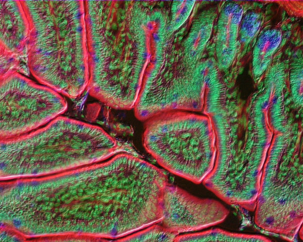
The advantages of a longer tube lens focal length becomes apparent when comparing systems having a 160-millimeter and a 200-millimeter tube lens focal length (Figure 3). Reduction in the off-axis diagonal wave flux angle can approach a significant percentage with the longer focal length optical system. The reduced angle of the oblique light rays produces correspondingly smaller shifts in both on-axis and off-axis rays passing through accessory components (DIC prisms, phase rings, dichroic mirrors, etc.), which improves the efficiency of the microscope. Dramatic enhancement in contrast levels observed with epi-fluorescence illuminators in infinity-corrected systems is attributed to the optical advantage of longer tube lens focal lengths. An example of the improvement in microscope images observed with infinity optics is presented in Figure 4, which illustrates a mouse intestine thin section labeled with three fluorescent dyes. The photomicrograph was recorded on a Nikon Eclipse E600 utilizing a CFI60 20x oil immersion objective of numerical aperture 0.75 and operating simultaneously in differential interference contrast and epi-fluorescence modes.
Figure 4 - Mouse Intestine Tissue (DIC/Fluorescence)
The objective focal length must be increased with infinity systems to preserve the same magnification when compared to older fixed tube length systems. A parfocal distance of 45 millimeters was used by all microscope manufacturers for many years with finite tube length systems, but this may be inadequate for high-performance infinity-corrected optics. For instance, a plan apochromatic 60x oil-immersion objective (one of the best performing finite objectives) can have over 10 individual lens elements and groups, resulting in a very tight fit for objectives constrained to a parfocal distance of 45 millimeters. When replaced by an infinity system that is subdivided into a separate objective (with an even greater number of optical elements) and tube lens, the focal length of the tube lens becomes equivalent to approximately 150 millimeters. To meet the full optical potential of the infinity system, the objective parfocal distance must be matched to the tube lens focal length. Thus, for a 200-millimeter focal length, the optimum parfocal distance is 60 millimeters, exceeding the older standardized length by 15 millimeters.
Interactive Tutorial - Tube Lens Focal Length
Infinity optical systems feature tube lengths between 200 and 250 millimeters.
Longer objective focal lengths utilized in infinity optical systems require correspondingly larger working distances to match. Increasing the parfocal distance of the objective is paramount to achieving a significant increase in working distance, especially for lower magnification objectives. For instance, with a 1x objective, the formula used to calculate magnification for infinity-corrected systems dictates that objective focal length should be the same as the tube lens. In a system with a 200-millimeter tube lens focal length, this would necessitate a longer parfocal distance in order to use an objective of this low magnification. Calculations reveal that a magnification as low as 0.5x can be obtained with 200-millimeter tube lens focal lengths, but that shorter focal lengths restrict the minimum objective magnification to values slightly above the 1x range.
Another consideration is the objective pupil diameter, which also must be increased for optimum performance with low-magnification objectives in optical systems having long tube lens focal lengths. The RMS standard objective thread size, 20.32 millimeters, limits the effective pupil diameter and maximum attainable numerical aperture in objectives so equipped. In order to produce higher numerical apertures when long tube lens focal lengths are being utilized, the objective thread size must be increased. The effective exit pupil diameter (D) necessary to achieve a desired numerical aperture is expressed by the formula:
Formula 1 - Exit Pupil Diameter
$$D = 2NA × f$$where NA is the numerical aperture and f is the objective focal length. Thus, for a 2x apochromatic objective having a focal length of 100 millimeters (utilizing a 200-millimeter focal length tube lens) and a numerical aperture of 0.10, the necessary exit pupil diameter (D) is 20 millimeters. Clearly, a smaller objective thread size limits objective numerical aperture at magnifications lower than 10x when designing infinity optical systems. Increasing the tube length above 200 millimeters requires an even greater objective exit pupil size, making this a limiting factor in the design of infinity-corrected microscopes.
Although all four major microscope manufacturers now offer infinity-corrected microscopes, Nikon is the only one that has made the transition to larger thread sizes, longer working distances, and an increased parfocal range. The company now offers a lineup of over 80 CFI60 objectives having a thread size of 25 millimeters, a parfocal distance of 60 millimeters, and designed to operate in microscopes having a 200-millimeter tube length. The acronym CFI stands for Chromatic aberration-Free (or Chrome Free) Infinity, and these objectives have the longest working distances and largest combinations of magnification at high numerical aperture currently available.
Contributing Authors
Related Nikon Products
Share this article:


