Innovations in Light Microscopy
Of all scientific instruments, probably none has had more thought and labor devoted to its improvement than the light microscope. Its evolution over the past centuries has been driven by scientists who wish to observe and measure phenomena that were smaller, fainter, (Figure 1) and deeper inside tissue than ever before.
Figure 1 - Bovine Pulmonary Artery Epithelial Cells
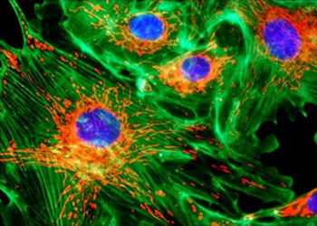
An example of the images produced by today's improved microscopes is presented in Figure 1, which illustrates a digitally captured multicolor fluorescence image of tissue culture cells taken on an Eclipse E600 microscope using the CFI60 40X fluorite objective and Nikon's DXM1200 digital camera.
A century ago, the microscope attained the limit of resolution predicted by classical theory of the nature of light. However, more than resolution was needed to allow the microscope to examine the inner workings of living cells in real time. Techniques formerly done in very few laboratories by the supreme masters of technique are now reduced to easy, routine clinical procedures. Microscope designers, carefully listening to microscopists, have brought about tremendous innovations. This paper summarizes recent advances in microscope design and focuses on how a recently developed optical system may enhance scientific progress.
Finite versus Infinite Optical Systems
In the days when biological microscopes were relatively uncomplicated, before epifluorescence and confocal techniques, there was little need to interpose thick optical components between the objective lens and eyepiece - the interlens space. The standard 160- or 170-mm tube length, the distance between the objective mounting flange and the seat for the eyepiece, served well for this. These instruments had convergent light in the interlens space. Metallurgists and geologists needed polarized light, and before the invention of wafer-thin polarizers, this required the insertion of massive prisms and other accessories in that space. One manufacturer in the 1930s, running out of room in the standard tube and plagued with aberration correction problems due to the prisms, first attempted a version of infinity optics to get around these troubles.
The term "infinity" means that the objective lenses are designed to project their images to infinity, not to some finite distance. The infinity optical system provides a region of parallel light between objective and eyepiece. With these systems, complex optical components can be inserted in that parallel light space without either introducing optical aberrations or reducing the free working distance of objectives. The system also retains the parfocality of sets of objectives (Figure 2). Presented in Figure 2 is a conceptual diagram of CFI60 optical path. Infinity optical systems consist of an objective, a tube lens to converge the beam, and an eyepiece lens. Modules and components can be placed in the parallel optical path between the objective and tube lens to create a totally flexible system without additional relay optics. The location of the image point remains constant, both axially and laterally, as does the alignment between the objective and the tube lens.
Figure 2 - CFI60 Optical Pathway
Of course, to form an image that we can see or record, the light from infinity-type objectives must be made convergent again by a tube lens, or second objective, between the parallel light space and the eyepieces. Usually two, and in one case as many as three, major optical components can be placed in this space without diminishing performance.
Accessories and inserted components can now be designed to achieve a magnification of exactly 1X, which is valuable when comparing several optical techniques with the same specimen. For instance, when optics for epifluorescence and differential interference contrast (DIC) are installed, there is still space for a third device - a magnification changer, a teaching head, a multiport assembly for two video cameras, or a drawing head for use with a digitizing pad to trace neurons.
In the classical microscope of years ago, the lens designer had the luxury of considering the objective and eyepiece together in the correction of lens aberrations, spherical and chromatic (both axial and lateral) aberrations, coma, astigmatism, and field curvature. Lateral chromatic aberration (LCA) is also known as chromatic difference of magnification - the formation of red, green, and blue images in the same focal plane, but with each color forming a different size image.
Traditionally, LCA has been very difficult to correct, and was often left uncorrected in the objective lens, to be compensated for in the eyepiece. The varieties of optical glasses and the computational techniques available years ago were insufficient for the task of correcting LCA within the objective. The insertion of thick components in the uncorrected interlens beam would further upset optical corrections.
Even today, not all manufacturers have achieved full correction of LCA within the objective. Newer glass formulas developed by Nikon Inc. (Melville, NY) have extremely low dispersion; thus, all aberrations are corrected within the objective itself. The company introduced the first completely corrected CF (chromatic aberration free) objectives in 1976, and this new technology continues to evolve in the CFI60 (chrome free infinity, 60-mm parfocal shoulder height) objectives, tube lenses, and eyepieces (Nikon). Of the various microscope systems designed with infinite tube length, only this one has combined the other design changes necessary to take full advantage of this concept.
New Lenses
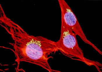
The design of an ideal objective for an infinity microscope system requires more than the usual number of lens elements, since the emergent beam must be focused at infinity. Add to that the demands of fluorescence techniques such as M-FISH (multicolor fluorescence in situ hybridization) (Figure 3), which are based on gathering as many photons as possible, and which require lenses of higher numerical aperture (NA). Add to this the requirements of confocal techniques for high NA, long working distance lenses that penetrate far into thick tissue. To meet these needs, today's lenses must have glass elements of larger physical diameter. Taken together, these requirements make old dimensional standards for lenses obsolete. The example presented in Figure 3 is a multicolor fluorescence image of fibroblasts, captured on film with an Eclipse E800 microscope using the CFI60 60X, NA 1.4 oil immersion objective.
Figure 3 - Fluorescence In-Situ Hybridization
A standard established in the mid-1800s by the Royal Microscopical Society in England set the diameter of the objective mounting threads. This dimension, while generous in its time and appropriate to the old brass microscopes, became a severe restriction on optical design. In addition, former industry standards for parfocal shoulder height - the distance from the specimen to the objective mounting flange - proved inadequate for the complexity of current designs. A new standard for these dimensions (25-mm thread diameter and 60-mm parfocal shoulder height, Nikon) makes innovative new lenses possible and ensures adequate room for improvement. The tube lens has a focal length of 200 mm, allowing lenses of very long working distance combined with high NA. These new standards and the tube lens make possible the free working distances of these objectives.
The CFI60 lenses have higher NAs than are usually available for standard magnifications, providing increased resolution of detail, greater light-gathering power, and high performance in confocal applications. A property shared by many of the objective lenses for the Eclipse instruments is longer-than-usual working distance. This allows thick specimens to be focused from top to bottom without fear of breaking the cover glass or damaging the objective itself. Applying immersion oil is easier, as is changing specimens. Thick-bottomed chambers are usable, and micromanipulation becomes possible with lenses of higher magnification.
In studies that are now revealing the internal mechanisms and dynamic activity of cells, every photon of fluorescent emission is precious. Gathering these with the greatest efficiency demands objectives of the highest possible numerical aperture. The Plan Fluor 40X NA 1.30 oil immersion lens combines magnification, high NA, field flatness, long working distance, and high ultraviolet transmission optimized for efficient work in fluorescence studies. For lenses of equal magnification, image brightness in epi-illumination systems is proportional to the fourth power of the numerical aperture. Calculations show that in comparing an ordinary high-dry lens of 0.65 NA with the 40X immersion lens of 1.30 NA, a 16-fold increase in brightness is obtained.
Better High-Dry Images
Many observations are made with the ordinary, nonimmersion 40X objective, the so-called high-dry lens. At this degree of magnification, an objective needs a fairly high NA to provide the richness of detail that 40X magnification should reveal. The lowest NA usually provided for 40X lenses is 0.65. Even at this NA, the optical performance of the microscope becomes dependent on the one optical component the lens designer and manufacturer cannot control - the coverslip on top of the specimen. Microscope manufacturers recommend a coverslip thickness of 0.17 mm, and they engrave it on the body of the objective (this corresponds to a #1 1/2 coverslip, in the terms of laboratory supply houses).
Many specimens are prepared with coverslips of other thicknesses. This is of little consequence for observations at low powers, but it has a strong influence at 40X and above. In lens designers' terms, the nonstandard coverslips upset the objective's spherical aberration; in users' terms, the image loses contrast and looks cloudy.
While 0.65 is the NA of ordinary 40X lenses, the higher-performance dry objectives can be as high as 0.95. These are so adversely influenced by coverslip thickness that a correction collar must be fitted on the objective. Image quality is optimized by turning it while observing image appearance. Turning the collar alters the internal spacing of some components of the objective, which, unfortunately, also changes the effective focus of the lens. In practice, one must simultaneously turn the collar with one hand and the fine focus knob with the other, while looking for the crispest image. Many users never master this technique. A patented design for high-NA, high-dry lenses (Nikon) has greatly minimized the focus shift, allowing for much easier optimization of image quality. For NAs higher than 0.95, immersion lenses are offered.
Universal Objectives
Every manufacturer lists different special objectives for observation techniques other than ordinary brightfield - techniques such as phase contrast, DIC, and fluorescence. Researchers using multiple techniques once needed to buy several of these objectives for any given magnification. Until now, it was not possible to design a single objective for these four purposes without significant losses in performance. Plan Fluor DLL lenses (Nikon) function in all four of these modes without sacrificing image quality. They provide savings in money, convenience, and space on the nosepiece
Lowest-Power Objective
In life, we usually observe a scene first in overview and then zoom in on the details that catch our eye. At the microscope, we start with low powers first, then move to higher powers. Pathologists, neurologists, and botanists are among the many life science professionals who frequently rely on low power for orientation and literally "getting the big picture." On many microscopes, however, the lowest power using a 10X objective and 10X eyepieces is 100X, quite a leap from natural size. Since microscopists are often reluctant to change to lower-power eyepieces, low-power objectives are the best choice for lower levels of magnification.
Figure 4 - Field of View in Low-Magnification Images
With the CFI60 0.5X objective, users can observe and photograph over a wide field of view. With an actual field of view of 50 mm, this objective is useful for macro observations of large specimens such as the tilia stem thin section illustrated in Figure 4. Compared to conventional infinity optical systems, the image area provided by the objective is more than five times greater in size. Actual-size photography is possible on 35-mm film.
Major manufacturers have provided objectives of approx. 4X, 2X, and even 1X power. The CFI Macroplan 0.5X objective, with its special accessories, presents a 5X image at the eyepieces, and will photograph a natural-size, 1X image on 35-mm film (see Figure 4). The lens offers an extremely high level of detail and chromatic correction, allowing the microscope to provide the widest magnification range possible.
Ergonomic Design
A microscope is much more than just optics; it is the laboratory instrument a scientist has the most physical contact with. When buying an instrument at which one may be sitting for hours at a time, it is vital to consider physical comfort. This is something that cannot be easily expressed in a specification sheet. It must be experienced firsthand.
In many older microscopes (and even in some more recent ones), the various controls were placed where they were most convenient for the manufacturer. This sometimes resulted in awkwardness or inconvenience.
All major manufacturers have been incorporating ergonomic considerations in the design of their stands, but the Eclipse instruments bring ergonomic considerations to a higher level. Extensive studies of how users sit at their instruments, measurements of convenient reaching distances, and determinations of comfortable arm and head positions were considered in the designs. Location of the stage handle and focus control knob on the E800 microscope is compared with conventional microscopes in Figure 5(a). By maintaining a natural position and having both hands equidistant from the body, strain is lessened. In addition, the stage handle and fine focus knob are located so they can be manipulated with one hand, enhancing comfortable observation. Erect and tilting eyepiece tubes are available on many of Nikon's microscopes (Figure 5(b)) to ensure that inspection efficiency rises and operator comfort is enhanced by the use of a system in a natural position.
Figure 5 - Ergonomic Microscope Design
Furthermore, the addition of components to the interlens space has not always been accomplished comfortably. If the components are merely stacked, as most manufacturers do, with the binocular viewing head and the eyepieces on top of them, the result often is an uncomfortably high viewing arrangement, with users craning their necks to peer through the eyepieces. In the Eclipse, up to three components are inserted in the interlens space without the need to change the instrument's constant, convenient eye position.
In the new stands, the most frequently used controls are put in the most convenient places for the microscopist, regardless of the ease of manufacturing. Controls used in conjunction with each other, such as stage movement and fine focus, have been placed where they can be adjusted with the fingers of the same hand. With forearms resting comfortably on the desktop, the most often used controls fall naturally under the fingertips. A much lower position of the stage makes slide changing convenient. Stage controls can be mounted on either side for left- or right-hand operation.
Other properties that are newly designed into the stands include greatly enhanced temporal and thermal stability, which is important for investigations extending over time, such as mitotic studies and embryology. Vibration damping is also increased to improve the resolution of captured images.
Conclusion
Has the ultimate light microscope been created? Though the new instruments on the market have brought the microscope to a high level of development, we will probably never reach that goal as long as scientific research continues. Future needs will require innovations that we cannot yet even foresee. But the best of today's instruments provide the user with vastly more performance and versatility than were possible just a few years ago.
Author
Martin L. Scott - Scientific Imaging, 231 Vassar St., Rochester, New York, 14607.
Photomicrographs
Related Nikon Products
Share this article:


